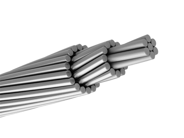
ALL ALUMINUM CONDUCTORS(AAC)
Aluminium Conductors (AAC) are made of Hard-Drawn aluminum wires
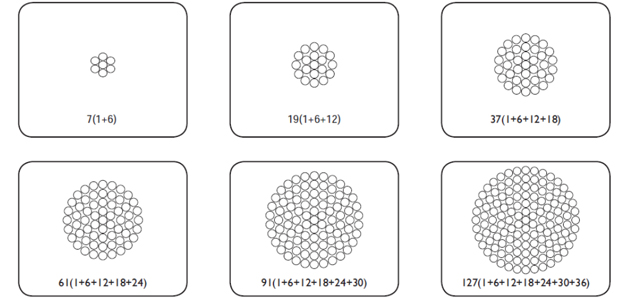
Construction
Technical Specifications
Quality Control
Application
Construction
All Aluminium Conductors
Application
AAC is mainly used in urban areas, where spacing is short and supports are close together. All-aluminium conductors consist of one or more strands of aluminium wire, depending on the intended use. AAC is also widely used in coastal regions due to its high corrosion resistance.
Description
Aluminium Conductors (AAC) are made of Hard-Drawn aluminum wires.
Standard
IEC 61089, DIN 48201-5, AS 1531, BS 215-1, BS EN 50182, ASTM B 231/B 231/M. Gost 83980.
Technical Specifications
All Aluminium Conductors
ASTM B 231/B 231M
IEC 61089
DIN 48201-5
BS 215-1
BS EN 50182
GOST 839-80
GB/T 1179
| Code Name | Nominal Area |
No./Nominal diameter of wires |
Approximate Overall Diameter |
Approximate Weight |
Nominal Breaking Load |
Nominal DC Resistance at 20°C |
|
| AWG or MCM | mm² | No./mm | mm | kg/km | KN | ohm/km | |
| Peachbell | 6 | 13.3 | 7/1.56 | 4.68 | 36.6 | 2.5 | 2.1477 |
| Rose | 4 | 21.1 | 7/1.96 | 5.88 | 58.2 | 3.9 | 1.3606 |
| Iris | 2 | 33.6 | 7/2.47 | 7.41 | 92.6 | 6.0 | 0.8567 |
| Pansy | 1 | 42.4 | 7/2.78 | 8.34 | 116.6 | 7.3 | 0.6763 |
| Poppy | 1/0.0 | 53.5 | 7/3.12 | 9.36 | 147.2 | 8.8 | 0.5369 |
| Aster | 2/0.0 | 67.4 | 7/3.50 | 10.50 | 185.7 | 11.1 | 0.4267 |
| Phlox | 3/0.0 | 85.0 | 7/3.93 | 11.79 | 233.9 | 13.5 | 0.3384 |
| Oxlip | 4/0.0 | 107.2 | 7/4.42 | 13.26 | 295.2 | 17.0 | 0.2675 |
| Valerian | 250.0 | 126.7 | 19/2.91 | 14.55 | 348.6 | 20.7 | 0.2274 |
| Sneezewort | 250.0 | 126.7 | 7/4.80 | 14.40 | 348.8 | 20.1 | 0.2269 |
| Laurel | 266.8 | 135.2 | 19/3.01 | 15.05 | 372.2 | 22.1 | 0.2125 |
| Daisy | 266.8 | 135.2 | 7/4.96 | 14.88 | 372.3 | 21.4 | 0.2125 |
| Peony | 300.0 | 152.0 | 19/3.19 | 15.95 | 418.3 | 24.3 | 0.1892 |
| Tulip | 336.4 | 170.5 | 19/3.38 | 16.90 | 469.5 | 27.3 | 0.1686 |
| Daffodil | 350.0 | 177.3 | 19/3.45 | 17.25 | 487.9 | 28.4 | 0.1618 |
| Canna | 397.5 | 201.4 | 19/3.67 | 18.35 | 554.9 | 31.6 | 0.1430 |
| Goldentuft | 450.0 | 228.0 | 19/3.91 | 19.55 | 627.6 | 35.0 | 0.1260 |
| Syringa | 477.0 | 241.7 | 37/2.88 | 20.16 | 664.8 | 38.6 | 0.1192 |
| Cosmos | 477.0 | 241.7 | 19/4.02 | 20.10 | 664.8 | 37.0 | 0.1192 |
| Hyacinth | 500.0 | 253.3 | 37/2.95 | 20.65 | 696.8 | 40.5 | 0.1136 |
| Zinnia | 500.0 | 253.3 | 19/4.12 | 20.60 | 697.1 | 38.9 | 0.1134 |
| Dahlia | 556.5 | 282.0 | 19/4.35 | 21.75 | 775.8 | 43.3 | 0.1018 |
| Mistletoe | 556.5 | 282.0 | 37/3.12 | 21.84 | 775.7 | 44.3 | 0.1016 |
| Meadowsweet | 600.0 | 304.0 | 37/3.23 | 22.61 | 836.3 | 47.5 | 0.0948 |
| Orchid | 636.0 | 322.3 | 37/3.33 | 23.31 | 886.9 | 50.4 | 0.0892 |
| Heuchera | 650.0 | 329.4 | 37/3.37 | 23.59 | 907.4 | 51.7 | 0.0871 |
| Flag | 700.0 | 354.7 | 61/2.72 | 24.48 | 975.8 | 57.1 | 0.0811 |
| Varbena | 700.0 | 354.7 | 37/3.49 | 24.43 | 975.7 | 55.4 | 0.0812 |
| Nasturtium | 715.5 | 362.6 | 61/2.75 | 24.75 | 998.5 | 58.4 | 0.0793 |
| Violet | 715.5 | 362.6 | 37/3.53 | 24.71 | 998.5 | 56.7 | 0.0794 |
| Cattail | 750.0 | 380.0 | 61/2.82 | 25.38 | 1046.0 | 60.3 | 0.0754 |
| Petunia | 750.0 | 380.0 | 37/3.62 | 25.34 | 1046.0 | 58.6 | 0.0755 |
| Lilac | 795.0 | 402.8 | 61/2.90 | 26.10 | 1110.0 | 63.8 | 0.0713 |
| Arbutus | 795.0 | 402.8 | 37/3.72 | 26.04 | 1109.0 | 61.8 | 0.0715 |
| Snapdragon | 900.0 | 456.0 | 61/3.09 | 27.81 | 1256.0 | 70.8 | 0.0628 |
| Cockscomb | 900.0 | 456.0 | 37/3.96 | 27.72 | 1256.0 | 68.4 | 0.0631 |
| Goldenrod | 954.0 | 483.4 | 61/3.18 | 28.62 | 1331.0 | 75.0 | 0.0593 |
| Magnolia | 954.0 | 483.4 | 37/4.08 | 28.56 | 1331.0 | 72.6 | 0.0594 |
| Camellia | 1000.0 | 506.7 | 61/3.25 | 29.25 | 1394.0 | 78.3 | 0.0568 |
| Hawkweed | 1000.0 | 506.7 | 37/4.18 | 29.26 | 1395.0 | 76.2 | 0.0566 |
| Larkspur | 1033.5 | 523.7 | 61/3.31 | 29.79 | 1442.0 | 81.3 | 0.0547 |
| Bluebell | 1033.5 | 523.7 | 37/4.25 | 29.75 | 1441.0 | 78.8 | 0.0547 |
| Marigold | 1113.0 | 564.0 | 61/3.43 | 30.87 | 1553.0 | 87.3 | 0.0510 |
| Hawthorn | 1192.5 | 604.2 | 61/3.55 | 31.95 | 1662.0 | 93.5 | 0.0476 |
| Narsissus | 1272.0 | 644.5 | 61/3.67 | 33.03 | 1774.0 | 98.1 | 0.0445 |
| Columbine | 1351.0 | 694.8 | 61/3.78 | 34.02 | 1884.0 | 104.0 | 0.0420 |
| Carnation | 1431.0 | 725.1 | 61/3.89 | 35.01 | 1997.0 | 108.0 | 0.0396 |
| Gladiolus | 1510.5 | 765.4 | 61/4.00 | 36.00 | 2108.0 | 114.0 | 0.0375 |
| Coreopsis | 1590.0 | 805.7 | 61/4.10 | 36.90 | 2216.0 | 120.0 | 0.0357 |
| Jassamine | 1750.0 | 886.7 | 61/4.30 | 38.70 | 2442.0 | 132.0 | 0.0324 |
| Cowslip | 2000.0 | 1013.0 | 91/3.77 | 41.47 | 2787.0 | 153.0 | 0.0286 |
| Sagebrush | 2250.0 | 1140.0 | 91/3.99 | 43.89 | 3166.0 | 167.0 | 0.0255 |
| Lupine | 2500.0 | 1267.0 | 91/4.21 | 46.31 | 3519.0 | 186.0 | 0.0229 |
| Bitterrot | 2750.0 | 1393.0 | 91/4.42 | 48.62 | 3872.0 | 205.0 | 0.0208 |
| Trillium | 3000.0 | 1520.0 | 127/3.90 | 50.70 | 4226.0 | 223.0 | 0.0193 |
| Bluebonnet | 3500.0 | 1773.0 | 127/4.22 | 54.86 | 4977.0 | 261.0 | 0.0165 |
| Code Name | Nominal Area |
No./Nominal diameter of wires |
Approximate Overall Diameter |
Approximate Weight |
Nominal Breaking Load |
Nominal DC Resistance at 20°C |
| mm² | No./mm | mm | kg/km | KN | ohm/km | |
| 10 | 10.0 | 7/1.35 | 4.05 | 27.4 | 2.0 | 2.8633 |
| 16 | 16.0 | 7/1.71 | 5.13 | 43.8 | 3.0 | 1.7896 |
| 25 | 25.0 | 7/2.13 | 6.39 | 68.4 | 4.5 | 1.1453 |
| 40 | 40.0 | 7/2.70 | 8.10 | 109.4 | 6.8 | 0.7158 |
| 63 | 63.0 | 7/3.39 | 10.17 | 172.3 | 10.4 | 0.4545 |
| 100 | 100.0 | 19/2.59 | 12.95 | 274.8 | 17.0 | 0.2877 |
| 125 | 125.0 | 19/2.89 | 14.45 | 343.6 | 21.3 | 0.2302 |
| 160 | 160.0 | 19/3.27 | 16.35 | 439.8 | 26.4 | 0.1798 |
| 200 | 200.0 | 19/3.66 | 18.30 | 549.7 | 32.0 | 0.1439 |
| 250 | 250.0 | 19/4.09 | 20.45 | 687.1 | 40.0 | 0.1151 |
| 315 | 315.0 | 37/3.29 | 23.03 | 867.9 | 52.0 | 0.0916 |
| 400 | 400.0 | 37/3.71 | 25.97 | 1102.0 | 64.0 | 0.0721 |
| 450 | 450.0 | 37/3.94 | 27.58 | 1239.8 | 72.0 | 0.0641 |
| 500 | 500.0 | 37/4.15 | 29.05 | 1377.6 | 80.0 | 0.0577 |
| 560 | 560.0 | 37/4.39 | 30.73 | 1542.9 | 89.6 | 0.0515 |
| 630 | 630.0 | 61/3.63 | 32.67 | 1738.3 | 100.8 | 0.0458 |
| 710 | 710.0 | 61/3.85 | 34.65 | 1959.1 | 113.6 | 0.0407 |
| 800 | 800.0 | 61/4.09 | 36.81 | 2207.4 | 128.0 | 0.0361 |
| 900 | 900.0 | 61/4.33 | 38.97 | 2483.3 | 144.0 | 0.0321 |
| 1000 | 1000.0 | 61/4.57 | 41.13 | 2759.2 | 160.0 | 0.0289 |
| 1120 | 1120.0 | 91/3.96 | 43.56 | 3093.5 | 179.2 | 0.0258 |
| 1250 | 1250.0 | 91/4.18 | 45.98 | 3452.6 | 200.0 | 0.0231 |
| 1400 | 1400.0 | 91/4.43 | 48.73 | 3866.9 | 224.0 | 0.0207 |
| 1500 | 1500.0 | 91/4.58 | 50.38 | 4143.1 | 240.0 | 0.0193 |
| Area | No./Nominal diameter of wires |
Approximate Overall Diameter |
Approximate Weight |
Nominal Breaking Load |
Nominal DC Resistance at 20°C |
|
| Nominal | Actual | |||||
| mm² | mm² | No./mm | mm | kg/km | KN | ohm/km |
| 16.0 | 15.9 | 7/1.70 | 5.10 | 43.0 | 2.8 | 1.8022 |
| 25.0 | 24.3 | 7/2.10 | 6.30 | 66.0 | 4.2 | 1.1810 |
| 35.0 | 34.4 | 7/2.50 | 7.50 | 94.0 | 5.8 | 0.8333 |
| 50.0 | 49.5 | 7/3.00 | 9.00 | 135.0 | 7.9 | 0.5787 |
| 50.0 | 48.4 | 19/1.80 | 9.00 | 133.0 | 8.5 | 0.5951 |
| 70.0 | 65.8 | 19/2.10 | 10.50 | 181.0 | 11.3 | 0.4372 |
| 95.0 | 93.3 | 19/2.50 | 12.50 | 256.0 | 15.7 | 0.3085 |
| 120.0 | 117.0 | 19/2.80 | 14.00 | 322.0 | 18.8 | 0.2459 |
| 150.0 | 147.1 | 37/2.25 | 15.80 | 406.0 | 25.3 | 0.1960 |
| 185.0 | 181.6 | 37/2.50 | 17.50 | 500.0 | 30.5 | 0.1588 |
| 240.0 | 242.5 | 61/2.25 | 20.30 | 670.0 | 39.5 | 0.1191 |
| 300.0 | 299.4 | 61/2.50 | 22.50 | 827.0 | 47.7 | 0.0965 |
| 400.0 | 400.1 | 61/2.89 | 26.00 | 1104.0 | 60.9 | 0.0722 |
| 500.0 | 499.8 | 61/3.23 | 29.10 | 1379.0 | 74.7 | 0.0578 |
| 625.0 | 626.2 | 91/2.96 | 32.60 | 1732.0 | 95.3 | 0.0462 |
| 800.0 | 802.1 | 91/3.35 | 36.90 | 2218.0 | 118.4 | 0.0360 |
| 1000.0 | 999.7 | 91/3.74 | 41.10 | 2767.0 | 145.8 | 0.0289 |
| Code Name | Nominal Area |
No./Nominal diameter of wires |
Approximate Overall Diameter |
Total Area | Approximate Weight |
Nominal Breaking Load |
Nominal DC Resistance at 20°C |
| mm² | No./mm | mm | mm² | kg/km | KN | ohm/km | |
| Midge | 22.0 | 7/2.06 | 6.18 | 23.3 | 64.0 | 4.0 | 1.2270 |
| Ant | 50.0 | 7/3.10 | 9.30 | 52.8 | 145.0 | 8.3 | 0.5419 |
| Fly | 60.0 | 7/3.40 | 10.20 | 63.6 | 174.0 | 9.9 | 0.4505 |
| Wasp | 100.0 | 7/4.39 | 13.17 | 106.0 | 290.0 | 16.0 | 0.2702 |
| Hornet | 150.0 | 19/3.25 | 16.25 | 157.6 | 434.0 | 25.7 | 0.1825 |
| Chafer | 200.0 | 19/3.78 | 18.90 | 213.2 | 587.0 | 32.4 | 0.1349 |
| Cockroach | 250.0 | 19/4.22 | 21.10 | 265.7 | 731.0 | 40.4 | 0.1083 |
| Butterfly | 300.0 | 19/4.65 | 23.25 | 322.7 | 888.0 | 48.8 | 0.0892 |
| Centipede | 400.0 | 37/3.78 | 26.46 | 415.2 | 1145.0 | 63.1 | 0.0694 |
| Code Name | Nominal Area |
No./Nominal diameter of wires |
Approximate Overall Diameter |
Total Area | Approximate Weight |
Nominal Breaking Load |
Nominal DC Resistance at 20°C |
| mm² | No./mm | mm | mm² | kg/km | KN | ohm/km | |
| Gnat | -- | 7/2.21 | 6.63 | 26.9 | 73.0 | 4.8 | 1.0643 |
| Mosquito | -- | 7/2.59 | 7.77 | 36.9 | 101.0 | 6.3 | 0.7749 |
| Ladybird | -- | 7/2.79 | 8.37 | 42.8 | 117.0 | 7.3 | 0.6678 |
| Bluebottle | -- | 7/3.66 | 10.98 | 73.6 | 201.0 | 11.8 | 0.3880 |
| Earwig | -- | 7/3.78 | 11.34 | 78.6 | 215.0 | 12.6 | 0.3638 |
| Grasshopper | -- | 7/3.91 | 11.73 | 84.1 | 230.0 | 13.5 | 0.3400 |
| Clegg | -- | 7/4.17 | 12.51 | 95.6 | 261.0 | 15.3 | 0.2989 |
| Beetle | -- | 19/2.67 | 13.35 | 106.4 | 292.0 | 18.1 | 0.2701 |
| Bee | -- | 7/4.90 | 14.70 | 132 | 361.0 | 21.1 | 0.2165 |
| Caterpillar | -- | 19/3.53 | 17.65 | 185.9 | 511.0 | 29.8 | 0.1546 |
| Spider | -- | 19/3.99 | 19.95 | 237.6 | 653.0 | 38.0 | 0.1210 |
| Moth | -- | 19/5.00 | 25.00 | 373.1 | 1025.0 | 59.7 | 0.0770 |
| Drone | -- | 37/3.58 | 25.06 | 372.4 | 1027.0 | 59.6 | 0.0774 |
| Maybug | -- | 37/4.09 | 28.63 | 486.1 | 1341.0 | 77.8 | 0.0593 |
| Scorpion | -- | 37/4.27 | 29.89 | 529.8 | 1461.0 | 84.8 | 0.0544 |
| Cicada | -- | 37/4.65 | 32.55 | 628.3 | 1733.0 | 100.5 | 0.0459 |
| Nominal Corss-section | Number of Wires | Wire Diameter | Calculated Cross-section | Overall Diameter | D.C. Resistance at 20 | Min. Breaking Load | Conductor Weight |
| mm² | mm | mm² | mm | Ω/km | kg/km | ||
| 10 | 7 | 1,35 | 10,0 | 4,05 | 28,631 | 1950 | 27,4 |
| 16 | 7 | 1,70 | 15,9 | 5,10 | 18,007 | 3021 | 43,0 |
| 25 | 7 | 2,13 | 24,9 | 6,40 | 11,498 | 4500 | 68,0 |
| 35 | 7 | 2,50 | 34,3 | 7,50 | 0,8347 | 5913 | 94,0 |
| 40 | 7 | 2,70 | 40,0 | 8,09 | 0,7157 | 6800 | 109,4 |
| 50 | 7 | 3,00 | 49,5 | 9,00 | 0,5784 | 8198 | 135,0 |
| 63 | 7 | 3,39 | 63,0 | 10,16 | 0,4544 | 10390 | 172,3 |
| 70 | 7 | 3,55 | 69,3 | 10,70 | 0,4131 | 11288 | 189,0 |
| 95 | 7 | 4,10 | 92,4 | 12,30 | 0,3114 | 14784 | 252,0 |
| 100 | 19 | 2,59 | 100,0 | 12,94 | 0,2877 | 17000 | 274,9 |
| 120 | 19 | 2,80 | 117,0 | 14,00 | 0,2459 | 19890 | 321,0 |
| 125 | 19 | 2,89 | 125,0 | 14,47 | 0,2301 | 21250 | 343,6 |
| 150 | 19 | 3,15 | 148,0 | 15,80 | 0,1944 | 24420 | 406,0 |
| 160 | 19 | 3,27 | 160,0 | 16,37 | 0,1798 | 26400 | 439,8 |
| 185 | 19 | 3,50 | 182,8 | 17,50 | 0,1574 | 29832 | 502,0 |
| 200 | 19 | 3,66 | 200,0 | 18,30 | 0,1438 | 32000 | 549,7 |
| 240 | 19 | 4,00 | 238,7 | 20,00 | 0,1205 | 38192 | 655,0 |
| 250 | 19 | 4,09 | 250,0 | 20,47 | 0,1150 | 40000 | 687,1 |
| 300 | 37 | 3,15 | 288,3 | 22,10 | 0,1000 | 47569 | 794,0 |
| 315 | 37 | 3,29 | 315,0 | 23,05 | 0,0915 | 51970 | 867,5 |
| 350 | 37 | 3,45 | 345,8 | 24,20 | 0,0833 | 57057 | 952,0 |
| 400 | 37 | 3,66 | 389,2 | 25,60 | 0,0740 | 63420 | 1072,0 |
| 450 | 37 | 3,90 | 449,1 | 27,30 | 0,0642 | 71856 | 1206,0 |
| 500 | 37 | 4,15 | 500,4 | 29,10 | 0,0576 | 80000 | 1378,0 |
| 550 | 61 | 3,37 | 544,0 | 30,30 | 0,0529 | 89760 | 1500,0 |
| 560 | 37 | 4,39 | 560,0 | 30,73 | 0,0531 | 89600 | 1542,2 |
| 600 | 61 | 3,50 | 586,8 | 31,50 | 0,0491 | 95632 | 1618,0 |
| 630 | 61 | 3,63 | 630,0 | 32,64 | 0,0458 | 100800 | 1738,4 |
| 650 | 61 | 3,66 | 641,7 | 32,90 | 0,0450 | 104575 | 1771,0 |
| 700 | 61 | 3,80 | 691,7 | 34,20 | 0,0417 | 112725 | 1902,0 |
| 710 | 61 | 3,85 | 710,0 | 34,65 | 0,0406 | 113600 | 1959,2 |
| 750 | 61 | 3,95 | 747,4 | 35,60 | 0,0386 | 119584 | 2062,0 |
| Nominal Area |
Total Area | No./Nominal diameter of wires |
Approximate Overall Diameter |
Approximate Weight |
Nominal Breaking Load |
Nominal DC Resistance at 20°C |
| mm² | mm² | No./mm | mm | kg/km | KN | ohm/km |
| 35.0 | 34.4 | 7/2.50 | 7.50 | 94.0 | 6.0 | 0.8333 |
| 50.0 | 49.5 | 7/3.00 | 9.00 | 135.3 | 8.4 | 0.5787 |
| 70.0 | 71.3 | 7/3.60 | 10.80 | 194.9 | 11.4 | 0.4019 |
| 95.0 | 95.1 | 7/4.16 | 12.50 | 260.2 | 15.2 | 0.3010 |
| 120.0 | 121.2 | 19/2.85 | 14.30 | 333.2 | 20.6 | 0.2374 |
| 150.0 | 148.1 | 19/3.15 | 15.80 | 407.0 | 24.4 | 0.1943 |
| 185.0 | 182.8 | 19/3.50 | 17.50 | 502.4 | 30.2 | 0.1574 |
| 210.0 | 209.9 | 193.75 | 18.80 | 576.8 | 33.6 | 0.1371 |
| 240.0 | 238.8 | 19/4.00 | 20.00 | 656.3 | 38.2 | 0.1205 |
| 300.0 | 297.6 | 19/3.20 | 22.40 | 819.8 | 49.1 | 0.0969 |
| 500.0 | 502.9 | 19/4.16 | 29.10 | 1385.5 | 80.5 | 0.0573 |
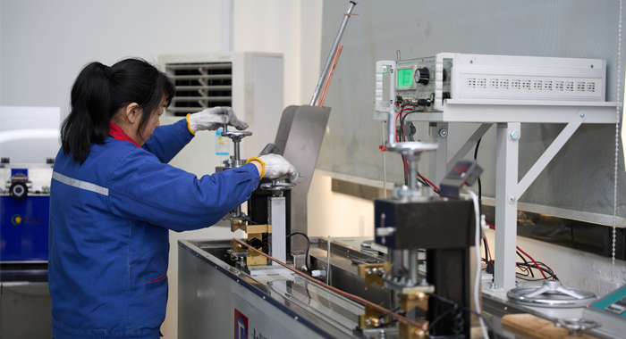
Quality Control
All Aluminium Conductors
Raw Material Testing
NPC has always chosen raw material suppliers who have a good reputation, possess stable supply capabilities and have passed international quality system certifications (such as ISO 9001). And establish a long-term cooperative relationship with it, forming a stable and reliable raw material supply chain.
We will ensure that all raw materials are subject to strict inspection procedures upon entry to the factory, and can only be stored in the warehouse after they have been confirmed to meet the standards.
Process Inspection
NPC has strict quality control procedures for each process in the cable production process.
Process documents: Develop detailed process flow and operation instructions to clarify the operating specifications and quality standards of each process.
Equipment calibration: Regularly calibrate key equipment such as wire drawing machines, stranding machines, extruders, and diameter gauges to ensure that the accuracy meets the requirements.
First piece confirmation: Before each batch of production, the first piece is trial-produced to confirm that the process parameters, product dimensions, electrical performance, etc. meet the standards before mass production can be carried out.
Finished Product
Inspectors conduct ex-factory inspections on cables according to relevant standards and corresponding product inspection specifications to ensure that each ex-factory product complies with the process regulations.
Application
All aluminium bare conductors are used for aerial distribution lines with relatively short spans, aerial feeders and bus bars of substations.
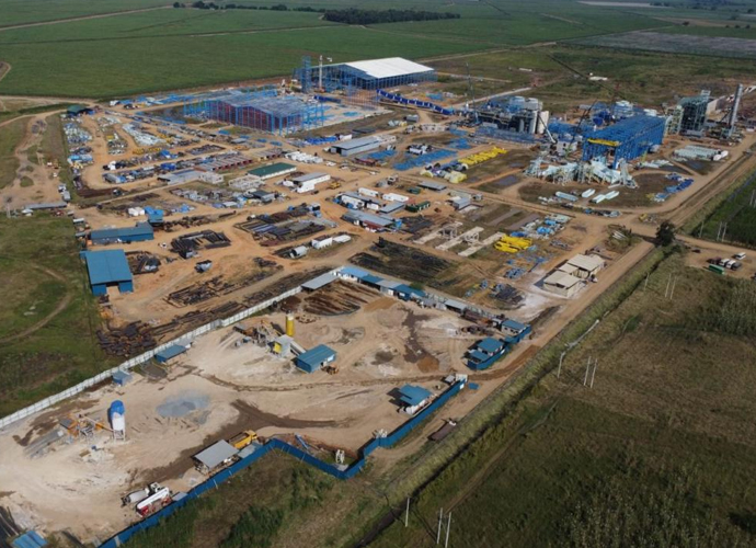
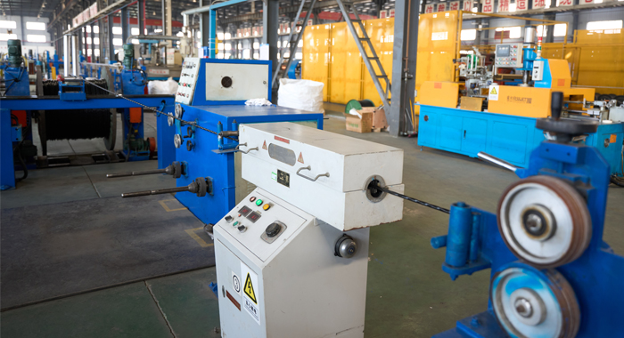
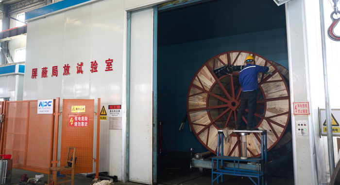
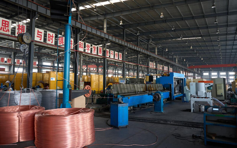
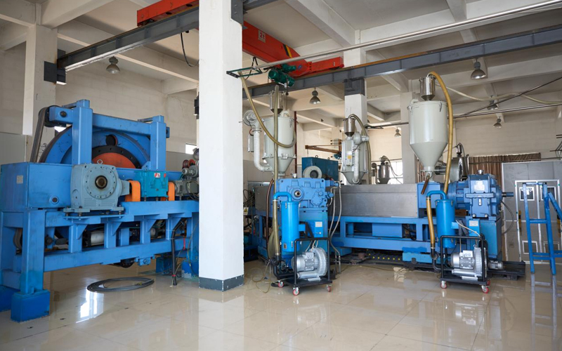
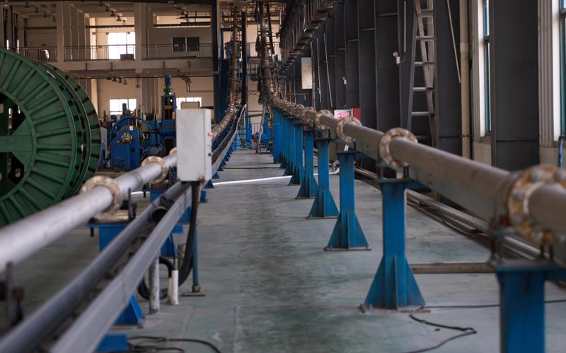
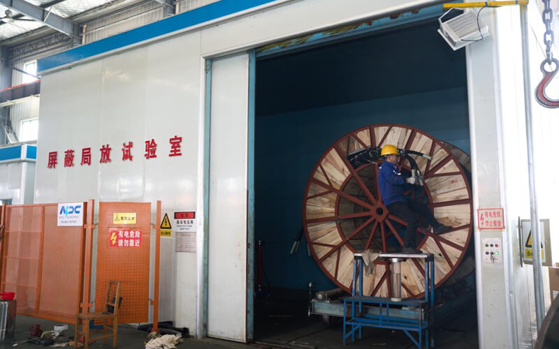
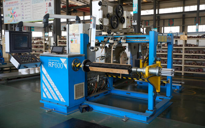
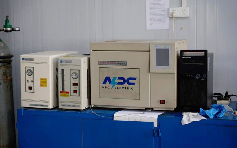
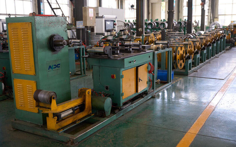
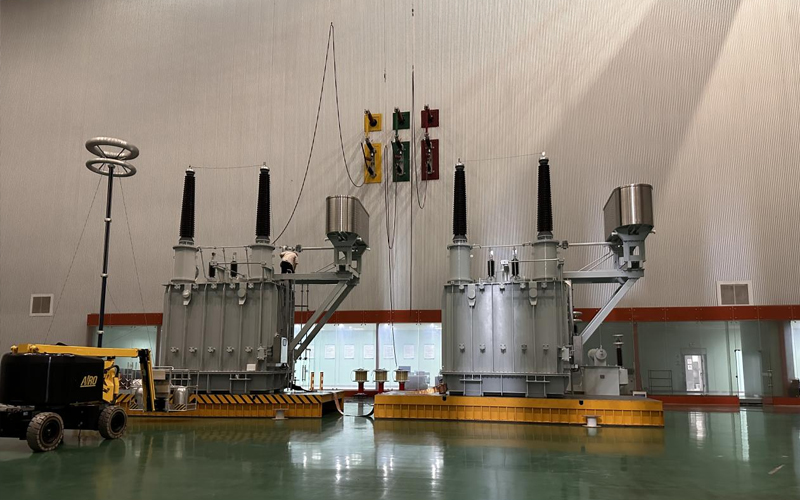
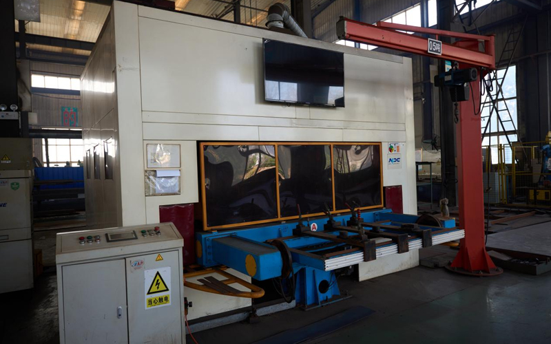
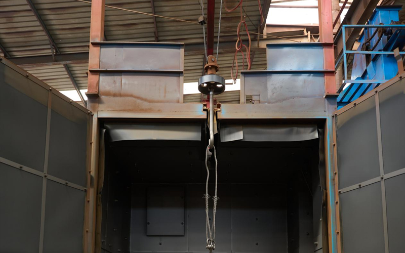
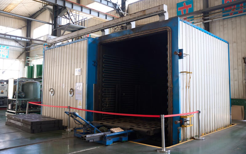
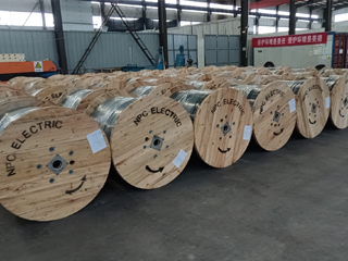
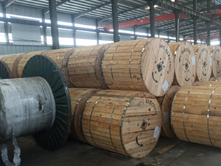
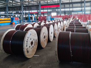
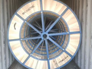
Factory View
● 30+ years of manufacturing experience
● ISO and UL certified production
● Customized cable and transformer solutions
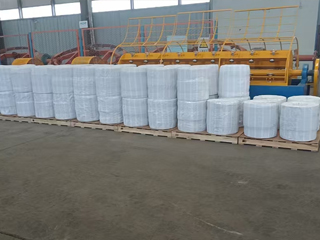
Product Packaging

Packaging and delivery site
Packaging and delivery site
Packaging and delivery site
Packaging and delivery site
Packaging and delivery site
Packaging and delivery site
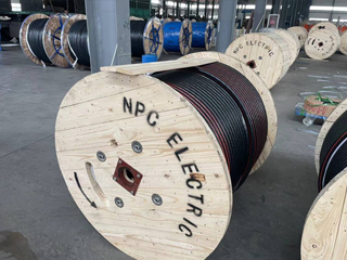
Packaging and delivery site
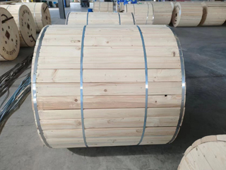
Packaging and delivery site
Related Products
FAQ From Customers
-
What are the advantages of power cables and overhead lines?(1) Reliable operation, because it is installed in a hidden place such as underground, it is less damaged by external forces, has less chance of failure, and the power supply is safe, and it will not cause harm to people; (2) The maintenance workload is small and frequent inspections are not required; (3) No need to erect towers; (4) Help improve power factor.
-
Which aspects should be considered when choosing the cross section of a power cable?(1) The long-term allowable working current of the cable; (2) Thermal stability once short circuited; (3) The voltage drop on the line cannot exceed the allowable working range.
-
What are the measures for cable fire prevention?(1) Use flame-retardant cables; (2) Use fireproof cable tray; (3) Use fireproof paint; (4) Fire partition walls and fire baffles are installed at cable tunnels, mezzanine exits, etc.; (5) Overhead cables should avoid oil pipelines and explosion-proof doors, otherwise local pipes or heat insulation and fire prevention measures should be taken.
-
What should be paid attention to during the transportation and handling of cables?(1) During transportation, loading and unloading, cables and cable reels should not be damaged. It is strictly forbidden to push the cable reels directly from the vehicle. Generally, cables should not be transported and stored flat. (2) Before transporting or rolling the cable reel, ensure that the cable reel is firm, the cable is wound tightly, the oil pipe between the oil-filled cable and the pressure oil tank should be fixed without damage, the pressure oil tank should be firm, and the pressure indication should meet the requirements.
-
What inspections should be carried out for the acceptance of cable lines?(1) The cable specifications should meet the regulations, the arrangement should be neat, no damage, and the signs should be complete, correct and clear; (2) The fixed bending radius of the cable, the related distance and the wiring of the metal sheath of the single-core power cable should meet the requirements; (3) The cable terminal and the middle head should not leak oil, and the installation should be firm. The oil pressure of the oil-filled cable and the meter setting should meet the requirements; (4) Good grounding; (5) The color of the cable terminal is correct, and the metal parts such as the bracket are completely painted; (6) There should be no debris in the cable trench, tunnel, and bridge, and the cover should be complete.
-
How many projects can cable engineering be divided into?(1) Construction site transportation: including the loading and unloading, transportation and empty vehicle return journey of engineering materials from the warehouse to the construction site. (2) Local engineering: including road excavation, tunnel, trench construction, etc. (3) Laying engineering: including laying, intermediate head production, lift cover plate, buried pipe, school tide, tractor head production, etc. (4) Two-end engineering: including the production and installation of support, suspension bridge and its foundation, the production of terminal heads, the installation of oil pressure and signal devices, and the electrical performance testing of various types. (5) Stopping works: including the production of oil-filled cable stop heads, the installation of fuel supply tanks, automatic drainage and signal devices, etc. (6) Grounding engineering: including installation of insulation joints, transposition boxes, protectors, and grounding boxes.
-
What tests and inspections should be carried out on power cables before laying?Before laying, check whether the type, specification and length of the cable meet the requirements and whether there is external force damage. Low-voltage cables use a 1000V megohmmeter to remotely measure the insulation resistance, and the resistance is generally not less than 10MΩ. High-voltage cables use a 2500V megger to measure the resistance. Generally not less than 400MΩ.
-
What are the factors that determine the long-term allowable current carrying capacity of the cable?(1) The long-term allowable working temperature of the cable; (2) The heat dissipation performance of the cable itself; (3) The condition of the cable installation and the heat dissipation conditions of the surrounding environment.
-
According to the difference of insulation and protective layer, what are the main types of commonly used low-voltage power cables?(1) Oil-impregnated paper insulated lead-clad (or aluminum-clad) power cable; (2) Non-drip oil-impregnated paper insulated power cable; (3) PVC insulated and sheathed power cable; (4) Cross-linked PVC insulated and PE sheathed power cable; (5) Cross-linked PVC insulated and sheathed power cable; (6) Rubber insulated power cables.
-
What are the requirements for the fire blocking of cable holes?For larger cable penetration holes, such as the cable penetration floor, etc., when using fireproof blocking materials to block, according to the actual situation, first coat four to six layers of fireproof paint on the cable surface, the length is about 1.5m below the hole, and then use fire-resistant The material is processed into a board-supporting fire-proof blocking material with a certain strength to ensure that it is firm after being blocked and is easy to disassemble and assemble when the cable is replaced. The plugging is dense and non-porous to effectively block smoke and fire.
-
What are the main properties of the insulation material of the power cable?(1) High breakdown strength; (2) Low dielectric loss; (3) Very high insulation resistance; (4) Excellent discharge resistance; (5) It has certain flexibility and mechanical strength; (6) Long-term insulation performance is stable.
-
What are the regulations for cable protection tubes?(1) When the cable needs to be laid through a protective pipe, the inner diameter of the pipe should not be less than 1.5 times the outer diameter of the cable, and the inner diameter of the concrete pipe, clay pipe, asbestos, and cement pipe should not be less than 100mm; (2) The bending radius of the cable tube should meet the requirements of the bending radius of the cable inserted; (3) Each pipe should not exceed three elbows at most, and there should be no more than two right-angle bends.
-
How to measure the outer diameter of the cable sheath?At five evenly distributed points on the circumference of the sheath, measure the outer diameter of the sheath and its average value. The average outer diameter is the outer diameter of the sheath.
-
How to connect copper core cables with different cross-sections?Copper core cables with different cross-sections can be connected by open-back weak copper pipes and connected by soldering, or pure copper rods can be connected into copper pipes according to different cross-sectional requirements and connected by crimping.
-
What are the insulating materials used to make cable terminal heads or intermediate joints?There are insulating glue, insulating tape, insulating tube, insulating gloves, insulating resin, etc.
Welcome your inquiry
Honesty, Integrity, Frugality, Activeness and Passion